
8501 LCR digital bridge can measure parameters such as resistance, capacitance, inductance and quality factor. Its main technical performance includes measurable parameters, measurement methods, measurement frequency, measurement frequency accuracy, maximum terminal voltage of elements, measurement speed, maximum waiting time for accurate readings after entering elements, display, measurement range, basic accuracy, limit resolution, basic accuracy conditions, input protection, power consumption, etc.
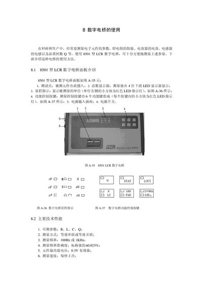
This manual describes the 8501 LCR digital bridge, a device for measuring resistance, inductance, capacitance and quality factor (Q) of electronic components. It explains the panel layout, including test clamps, a 4‑digit LED display, range indicators and six function keys, as well as power connection and safety notes.
The document also details the measurement methods, selectable frequencies (100 Hz or 1 kHz), accuracy, range limits, and operation of control keys such as LC‑R, SER‑PAR, LOCK and BIAS. Guidance on proper component connection, range locking, and troubleshooting low‑accuracy indications is provided. This manual is written in Chinese.
| Measurable parameters | R, L, C, Q |
|---|---|
| Measurement frequency options | 100 Hz or 1 kHz |
| Frequency accuracy | ±0.025 % of nominal |
| Maximum component voltage | 0.3 V RMS |
| Measurement speed | 2 readings per second |
| Resistance range | 0.000 Ω – 100 MΩ |
| Inductance range | 0.0 µH – 9999 H |
| Capacitance range | 0.0 pF – 9999 µF |
| Q factor range | 0.00 – 99 |
| Basic accuracy | ±0.25 % of reading ±1 digit |
| Resolution | R 0.001 Ω, L 0.1 µH, C 0.1 pF |
| Power consumption | ≤25 W |
Press the 100Hz‑1kHz button; choose 100 Hz for low‑value components and 1 kHz for high‑value components as indicated in the manual.
The basic accuracy is ±0.25 % of the reading plus or minus one digit.