
PCL-724 is a 24-way digital input/output card that provides 24 parallel digital input/output ports. Simulating programmable parallel I/O interface chip 8255 mode 0, with a 50-pin interface, pin definitions are fully compatible with Opto-22 modules. PCL-724 is particularly suitable for SSR I/O mode control. The 0th bit of one port can generate an interrupt IRQ2~7.
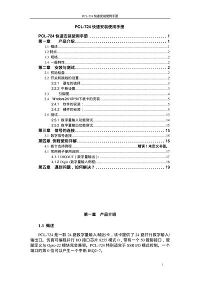
This manual introduces the Advantech PCL-724, a 24‑channel TTL digital I/O card compatible with Opto‑22 modules. It outlines the card’s features, electrical specifications, and general characteristics.
The guide walks users through initial checks, jumper and switch settings, hardware and software installation, functional testing of digital inputs and outputs, example programs, and a troubleshooting section with support resources. This manual is written in Chinese.
| Input logic high voltage | 2.0~5.25 V |
|---|---|
| Input high current | 20.0 µA |
| Input low current | -0.2 mA |
| Output high current | -15.0 mA |
| Output low current | 24.0 mA |
| Output logic high voltage (min) | 2.4 V |
| Output logic low voltage (max) | 0.4 V |
| Transfer rate (typical) | 300 Kbytes/s |
| Operating temperature range | 0 °C to –60 °C |
| Interface | 50‑pin flat cable connector |
| Dimensions | 12 mm × 100 mm |
The PCL-724 provides 24 parallel digital input and output channels.
The base address is set using the 8‑bit DIP switch SW1 on the card; the default address is 0x2C3.
Install the driver from the supplied CD using Device Manager, or download it from Advantech’s support website.