
M62256FP is a semiconductor integrated circuit designed to control the battery charger. This IC controls not only all the time sequence needed for battery charging, but also gives full support for detection of battery temperature, protection over current and voltage, and safety timer, etc. It is also a simple matter to charge Ni-Cd, Ni-MH batteries by adding a small peripheral components to this IC. This IC has a feedback controlling of the charge current and the output voltage.
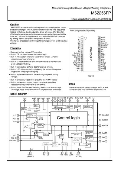
The M62256FP is a single‑chip battery charger control IC designed by Mitsubishi for low‑voltage (3 V) operation. It integrates a CR oscillator, initialization and safety timers, D/A converter, LED driver, temperature detection, and protection circuits for over‑voltage, over‑current and over‑heat conditions.
The document provides pin assignments, absolute maximum ratings, electrical characteristics, internal voltage set‑up values, recommended operating ranges, and detailed functional descriptions for charging, adapter mode and discharge operations.
| Power supply voltage range | 3.0 V – 15.0 V |
|---|---|
| LED drive current | 20 mA max |
| Maximum power dissipation | 650 mW |
| Operating temperature range | -20 °C to +75 °C |
| Quick charge current | 0.8 A – 2 A |
| Trickle charge current | 80 mA – 200 mA |
Vref1 output voltage is typically 1.25 V (range 1.18 V – 1.32 V).
Over‑voltage detection stops charging when the battery voltage reaches 9.5 V or higher.
The Vref2 terminal is used for temperature detection.
OCSET sets the over‑current detection threshold value in adapter mode.