
The MAX6877 evaluation board (EV kit) is a fully assembled and tested multi-voltage power tracking/sorting/management controller that demonstrates the capabilities of the MAX6877 controller. During power-up and power-down, the MAX6877 ensures tracking and sorting of up to three voltages. Once the input voltage is stable, the voltage tracking function ensures that all output voltages of the power supply rise or fall at the same rate, and the voltage sorting function sequentially turns on the outputs. The evaluation board circuitry provides FAULT and PG/RST output signals to indicate fault and power-ready conditions, respectively. The circuit’s timing parameters and voltage thresholds can be reconfigured. The evaluation board is designed to handle currents of up to 10A per channel.
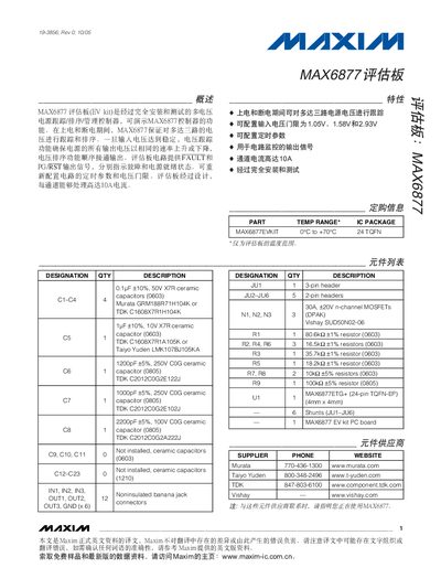
This manual describes the MAX6877 evaluation board, a fully assembled and tested surface‑mount circuit that demonstrates the MAX6877 power‑tracking, sequencing, and management controller. It explains how to connect power supplies, configure jumpers, and monitor the board's status signals.
The document includes detailed tables for jumper settings, timing parameter calculations, and safety notes. It also lists the configurable input voltage thresholds, channel current capability, and the three output channels (OUT1‑OUT3) with their associated PG/RST and FAULT signals. This manual is written in Chinese.
| Input voltage threshold IN1 | 1.05 V |
|---|---|
| Input voltage threshold IN2 | 1.58 V |
| Input voltage threshold IN3 | 2.93 V |
| Maximum channel current | 10 A per channel |
The thresholds can be set to 1.05 V for IN1, 1.58 V for IN2, and 2.93 V for IN3.
Each channel can handle up to 10 A of current.
Install jumper JU2 in the not‑installed position (connect to ABP) as shown in the JU2 jumper table.