
The SSI-UART module is a module that converts SSI synchronous serial data into general asynchronous serial (UART) data. It can easily connect SSI encoders with commonly used control systems in the industrial control field such as PC, industrial computer, DSP, microcontroller, etc.
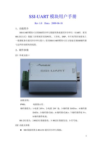
The SSI-UART module converts SSI synchronous serial data to standard RS‑232 asynchronous UART, allowing easy connection of SSI encoders to PCs, industrial PCs, DSPs, or microcontrollers. It supports multiple SSI clock rates, data formats, and encoder address configuration for industrial control applications.
The manual covers hardware parameters, communication protocol, configuration of clock speed, data sending mode, data format conversion, encoder address and supply voltage, as well as a test software tool and contact information for sales and technical support. This manual is written in Chinese.
| Supported SSI clock rates | 125 kHz, 250 kHz, 500 kHz, 1 MHz |
|---|---|
| RS‑232 format | 115200 bps, 8 data bits, 1 stop bit, no parity |
| Supply voltage range | 18‑30 V DC |
| Maximum current consumption | ≤ 60 mA |
| Operating temperature | -40 °C ~ -75 °C |
| Dimensions | 80 mm × 65 mm × 25 mm |
| Default encoder address | 0x03 |
Short or open the jumpers CLKMD1 (J5‑9/10) and CLKMD0 (J5‑11/12) according to the desired rate table.
Short or open the MODEM jumpers (J5‑1 and J5‑2); shorted selects active sending, open selects inquiry mode.
The module uses 115200 bps, 8 data bits, 1 stop bit, and no parity.
Adjust jumpers A1 (J5‑7/8) and A0 (J5‑5/6) to set the address; the default is 0x03.