
This document describes the features and characteristics of the XMT61X series intelligent PID temperature controller, including compatibility with multiple signal inputs, optional control output modes, and powerful self-tuning function.
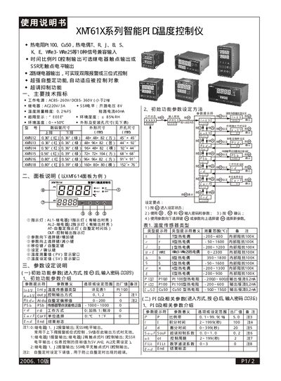
This manual describes the XMT61X series intelligent PID temperature controller, its main technical specifications, supported temperature sensors, and panel layout. It includes details on power supply, relay ratings, measurement accuracy, and environmental limits.
The document explains how to set initial parameters, configure PID and related settings, use the self‑tuning function, and connect the controller for heating or cooling applications. An application example shows wiring and parameter values for controlling a furnace temperature. This manual is written in Chinese.
| Power supply | AC85‑260V / DC85‑360V (≤2W) |
|---|---|
| Relay rating | AC220V / 3A |
| SSR open‑circuit voltage | 8 V |
| Temperature measurement accuracy | 0.2 % FS |
| Short‑circuit current | 40 mA |
| Over‑limit display code | EEEE |
| Ambient humidity limit | ≤85 % RH |
| Ambient temperature range | 0 ℃ ~ +50 ℃ |
| Supported temperature sensors | Pt100, Cu50, T, R, J, B, S, K, E, WRe3‑WRe25 |
| Control output options | Relay contact output or SSR level output |
| Number of relay outputs | 2 |
Long‑press the key until the “AT” light flashes; the controller enters self‑tuning mode, and when the AT light turns off the tuning is complete.
In measurement mode, press the increase key to raise the setpoint (SV) or the decrease key to lower it.
AL1 indicates relay J1 output, AL2 indicates relay J2 output, and AT flashes during the self‑tuning process.