
Key facts
- Manuals
- 11
- Models
- 2
- Languages
- EN
- Last added
- 2012-06-11
Zarlink models by category
Featured Zarlink manuals
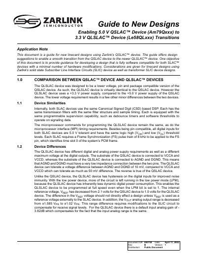
Zarlink Am79Qxxx to Le58QLxxx Transition Application Note
The guide explains how to transition line‑card designs from the 5 V QSLAC device to the lower‑voltage QLSLAC device while keeping software compatibility and minimizing hardware changes. It covers power‑supply requirements, subscriber line interface circuit options, and microprocessor interface timing.
Key topics include device similarities and differences, power‑supply considerations, solid‑state and transformer SLIC designs, filter‑coefficient computation, and interface specifications such as MPI timing and frame‑synchronization requirements.
Covers: Comparison Between QSLAC and QLSLAC Devices · Power Supply Considerations · Subscriber Line Interface Circuit Considerations · Design with Zarlink Solid‑State SLIC Devices · Design with Transformer SLIC Devices · SLAC Device Coefficients
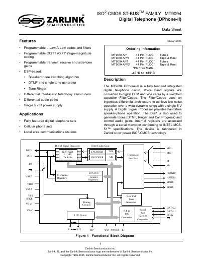
Zarlink MT9094 DPhone-II Digital Telephone Datasheet
The MT9094 DPhone‑II is a fully featured integrated digital telephone circuit that converts voice‑band signals to PCM and back using a switched‑capacitor filter/codec. It operates from a single 5 V supply and includes a DSP for hands‑free speaker‑phone operation, DTMF generation, tone ringer, and programmable audio gains.
The datasheet provides a functional block diagram, a complete 44‑pin PLCC pinout, register maps, and detailed specifications such as audio gain ranges, codec companding options, and serial ST‑BUS interface parameters. It also describes the DSP micro‑programs and optional features like offset nulling and high‑pass filtering.
Covers: Features · Pin Connections · Functional Block Diagram · Filter‑CODEC · Digital Signal Processor · Register Summary
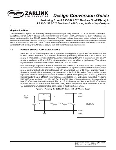
Zarlink Am79Qxxx to Le58QLxxx Design Conversion Guide
The document provides step‑by‑step instructions for redesigning line‑card circuits that currently use 5.0 V QSLAC devices so they can operate with 3.3 V QLSLAC devices. It details power‑supply considerations, interface timing changes, and required gain modifications to maintain performance.
Key sections include Power Supply Considerations, Interface Considerations (MPI, PCM, Master Clock, SLIC control), Subscriber Line Interface Circuit considerations, SLAC Coefficients, and Comparative Transmission Performance with example simulations.
Covers: Power Supply Considerations · Interface Considerations · Subscriber Line Interface Circuit Considerations · SLAC Coefficients · Comparative Transmission Performance · Conclusion
Latest Zarlink manuals
ZARLINK Semiconductor ZL49010/1 ZL49020/1 ZL49030/1 Wide Dynamic Range DTMF Receiver Data Sheet
ZL490xx is a family of high performance DTMF receivers which decode all 16 tone pairs into a 4-bit binary code. These devices incorporate an AGC for wide dynamic range and are suitable for end-to-end signalling.
ZARLINK SL2150D handbook
The SL2150D is a wide dynamic range front end for tuner applications. It offers two buffered outputs from a single input, where both paths contain an independently controllable AGC and disable facility.
ZARLINK SL1935 handbook
The SL1935 is a complete single chip bus controlled Zero IF tuner and operates from 950 to 2150MHz. It includes an on-board low phase noise PLL frequency synthesiser and low noise LNA/AGC. The SL1935 is intended primarily for application in digital satellite Network Interface Modules and performs the complete tuner function. The device contains all elements necessary, including low noise LNA/AGC, low phase noise PLL frequency synthesiser and digital baseband processor.
ZARLINK SP8904(MP) handbook
SP8904 is a very high-speed low-power prescaler for professional applications. The dividing elements are static D type flip flops and therefore allow operation down to DC if the drive signal is a pulse waveform with fast risetime. The output stage has a differential current output and provides a direct drive into a 50 ohm load.
ZARLINK SP5730 Manual
The SP5730 is a single chip frequency synthesizer designed for tuning systems up to 1.3GHz and is optimized for digital terrestrial applications. The RF preamplifier interfaces directly with the RF programmable divider, which is of MN1A construction so giving a step size equal to the loop comparison frequency and no RF prescaler phase noise degradation over the full RF operating range. The comparison frequency can be obtained either from an on-chip crystal controlled oscillator, or from an external source. The oscillator frequency, fREF, or phase comparator frequency, fCOMP, can be switched to the REF/COMP output providing a reference for a second frequency synthesizer. The synthesizer is controlled via an I2C bus and is fast mode compliant with 3.3V and 5V logic levels.
ZARLINK KESTX01 Manual
The KESTX01 is a single chip ASK (Amplitude Shift Key) transmitter IC. It is designed to operate in a variety of low power radio applications including keyless entry, general domestic and industrial remote control, RF tagging and local paging systems.
ZARLINK ZL10310/ZL10311 Digital Television DVB-T-On-a-Chip Processor handbook
This document describes the features and characteristics of a digital television processor, including a digital television system-on-chip, on-chip DVB-T COFDM demodulator, multiple video output interfaces, low power consumption, support for external MPEG-2 transport streams, conditional access, etc.
Zarlink Am79Qxxx to Le58QLxxx Transition Application Note
Application Note 17 pages · 354 KB · ENThis application note provides design guidance for moving from 5 V QSLAC (Am79Qxxx) to 3.3 V QLSLAC (Le58QLxxx) devices, covering power, SLIC, interface…
Zarlink MT9094 DPhone-II Digital Telephone Datasheet
Datasheet 36 pages · 634 KB · ENThe Zarlink MT9094 DPhone-II datasheet details features, pinout, functional blocks, and specifications of this integrated digital telephone IC.
Zarlink Am79Qxxx to Le58QLxxx Design Conversion Guide
Application Note 12 pages · 588 KB · ENThis guide explains how to convert existing designs using Zarlink QSLAC devices to the lower‑voltage QLSLAC devices, covering power supply, interface, and…
ZARLINK ZL30100 T1/E1 System Synchronizer Manual
Which document do I need?
Application Note
How to use the product for one specific task, with worked examples.
Datasheet
Ratings, dimensions and ordering codes, for selection and design work.
Questions answered in Zarlink manuals
What power supply voltage is required for the QSLAC device?
The QSLAC device requires a 5.0 V power supply within a ±5 % tolerance.
From: Zarlink Am79Qxxx to Le58QLxxx Transition Application Note
How much current must the power supply provide for each device?
Each device should be able to source at least 55 mA of current.
From: Zarlink Am79Qxxx to Le58QLxxx Transition Application Note
What supply voltage does the MT9094 require?
The device operates from a single 5 V supply.
How many pins does the MT9094 have and what package is used?
It is supplied in a 44‑pin PLCC package.
Which voltage regulator is recommended for converting a 5 V supply to 3.3 V?
The document recommends National Semiconductor’s LM1117‑3.3 regulator, which can source up to 800 mA.
What resistor value adjustment is needed for TSCA/TSCB pull‑up when using a 3.3 V supply?
The pull‑up resistors should be reduced from 360 Ω to 240 Ω to maintain similar rise‑time.