
Key facts
- Brand
- Zarlink
- Model
- LE58QLXXX
- Industry
- Industrial
- Documents
- 2
- Languages
- EN
- Last added
- 2012-02-15
Start here
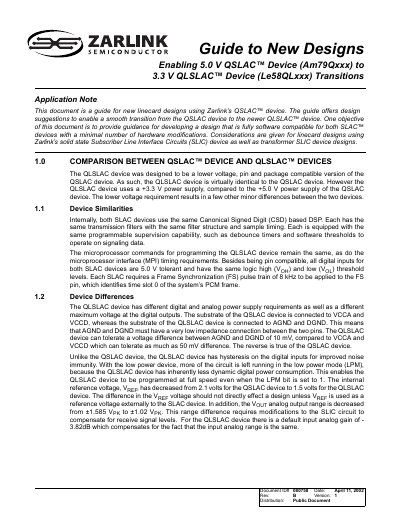
Zarlink Am79Qxxx to Le58QLxxx Transition Application Note
The guide explains how to transition line‑card designs from the 5 V QSLAC device to the lower‑voltage QLSLAC device while keeping software compatibility and minimizing hardware changes. It covers power‑supply requirements, subscriber line interface circuit options, and microprocessor interface timing.
Key topics include device similarities and differences, power‑supply considerations, solid‑state and transformer SLIC designs, filter‑coefficient computation, and interface specifications such as MPI timing and frame‑synchronization requirements.
Zarlink LE58QLXXX specifications
| QSLAC power supply voltage | 5.0 V ±5% |
|---|---|
| QLSLAC power supply voltage | 3.3 V ±5% |
| Current per device | ≥ 55 mA |
| Digital input voltage tolerance | 5.0 V tolerant |
| Frame‑synchronization pulse | 8 kHz |
Source: Zarlink Am79Qxxx to Le58QLxxx Transition Application Note
All Zarlink LE58QLXXX documents by type
How to use the product for one specific task, with worked examples.
Questions answered in these manuals
What power supply voltage is required for the QSLAC device?
The QSLAC device requires a 5.0 V power supply within a ±5 % tolerance.
From: Zarlink Am79Qxxx to Le58QLxxx Transition Application Note
How much current must the power supply provide for each device?
Each device should be able to source at least 55 mA of current.
From: Zarlink Am79Qxxx to Le58QLxxx Transition Application Note
Which voltage regulator is recommended for converting a 5 V supply to 3.3 V?
The document recommends National Semiconductor’s LM1117‑3.3 regulator, which can source up to 800 mA.
What resistor value adjustment is needed for TSCA/TSCB pull‑up when using a 3.3 V supply?
The pull‑up resistors should be reduced from 360 Ω to 240 Ω to maintain similar rise‑time.