
Key facts
- Manuals
- 1
- Languages
- EN
- Last added
- 2026-11-06
Featured TeamWavelength manuals
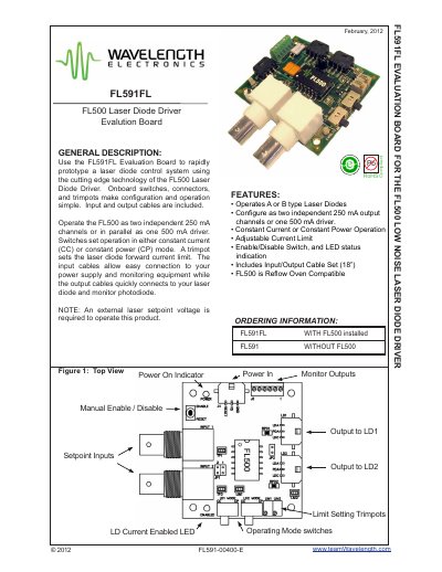
TeamWavelength FL591FL Evaluation Board User Manual
This document provides step-by-step instructions for configuring and operating the FL591FL Evaluation Board with the FL500 Laser Diode Driver. It covers setup for individual or parallel operation, constant current or constant power modes, power supply connections, and laser diode current limit adjustments. The board includes onboard switches, connectors, and trimpots for easy configuration. It is designed for prototyping laser diode control systems using the FL500 driver.
The manual includes schematic diagrams, safety notes, and operational guidelines to ensure safe and effective use of the board. It also provides information on compatible laser diode types (A and B) and how to simulate laser diode loads for initial testing without risking damage to expensive components.
Covers: General Description · Features · Ordering Information · Schematic Diagram · Configuring the Evaluation Board · Operating Mode Selection
Latest TeamWavelength manuals
TeamWavelength FL591FL Evaluation Board User Manual
User Manual 14 pages · 369 KB · ENUser manual for the FL591FL Evaluation Board, used to prototype laser diode control systems with the FL500 driver.
Which document do I need?
User Manual
Day-to-day operation, settings and troubleshooting. Start here if the product is already set up.
Questions answered in TeamWavelength manuals
What laser diodes are compatible with the FL591FL?
The FL591FL supports only Type A or B laser diodes. Type C is not supported.
How do I connect the laser diode and monitor photodiode?
With power removed, connect the 3-wire output cable to the laser diode. Use LDA for laser diode anode, PDA for photodiode anode, and LDC for laser diode cathode.