
Key facts
- Brand
- Yamatake
- Model
- SDC20/21
- Category
- Automation control Equipment
- Industry
- Industrial
- Documents
- 2
- Languages
- EN
- Last added
- 2026-09-28
Start here
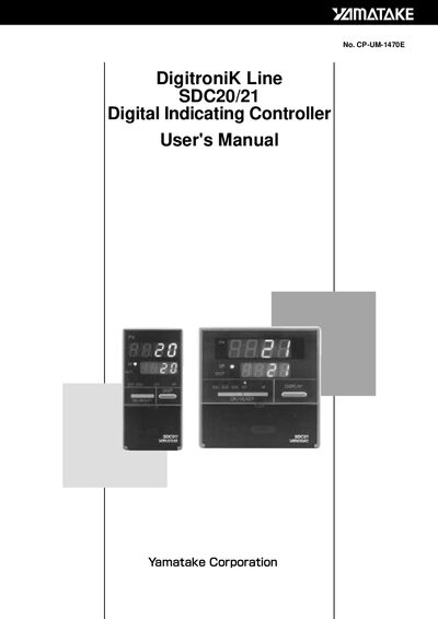
Yamatake SDC20/21 Digital Indicating Controller User Manual
This manual covers safety precautions, component identification, and installation guidelines for the Yamatake SDC20/21 digital indicating controller. It explains proper mounting, wiring, grounding, and environmental limits.
Detailed sections describe setup of parameters, operation of keys, troubleshooting alarms, and full technical specifications, along with appendices for part numbers and term definitions.
Yamatake SDC20/21 specifications
| Supply voltage | 85 to 264 Vac |
|---|---|
| Frequency | 50/60 Hz |
| Power rating | 18 VA maximum |
| Operating temperature | 0 to 50 °C |
| Humidity range | 10 to 90% RH |
| Vibration frequency | 10 to 60 Hz |
| Acceleration limit | 2 m/s² maximum |
| Relay output type | 0D Relay output |
| RS‑485 communication | Supported |
Source: Yamatake SDC20/21 Digital Indicating Controller User Manual
All Yamatake SDC20/21 documents by type
Day-to-day operation, settings and troubleshooting. Start here if the product is already set up.
Questions answered in these manuals
What safety step must be taken before connecting wiring to the controller?
Turn the mains power supply OFF before connecting or disconnecting any wiring.
From: Yamatake SDC20/21 Digital Indicating Controller User Manual
How should the controller be mounted?
The controller must be mounted into a panel to limit operator access to the rear terminals.
From: Yamatake SDC20/21 Digital Indicating Controller User Manual
What supply voltage should be used with the SDC20/21?
The device is rated for a supply voltage of 100 to 240 V AC.
From: Yamatake SDC20/21 Digital Instruction Regulator User Manual
How must the GND terminal be wired?
The GND terminal must be connected before any other wiring is performed.
From: Yamatake SDC20/21 Digital Instruction Regulator User Manual