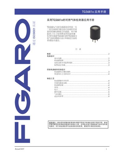
Application guide for Figaro TGS681x gas sensors covering circuit design, PCB layout, manufacturing, calibration and storage.
About this manual
This manual provides technical recommendations for designing and manufacturing gas detectors that use Figaro's TGS6810 and TGS6812 catalytic combustion sensors. It covers circuit schematics, PCB and enclosure design, sensor positioning, fault detection, and calibration procedures.
Additional sections describe manufacturing processes, pre‑heating, final assembly, gas calibration, and proper storage conditions to ensure long‑term stability and safety of the detectors. This manual is written in Chinese.
What's inside
- Circuit Design
- Sensor Fault
- Alarm Prevention During Heating
- PCB and Enclosure Design
- Manufacturing Process
- Sensor Operation and Storage
- Calibration
- Final Assembly
Specifications
| Recommended resistor values (basic circuit) | R1 = 1.2 kΩ, R2 = 1.2 kΩ, VR = 100 Ω |
|---|
| Fault detection voltage threshold | Vout ≤ 0.2 V |
|---|
| Alarm delay recommendation | Delay 30 s or longer until Vout ≤ 2 V |
|---|
| Pre‑heat time for accuracy‑oriented applications | 2 weeks |
|---|
Frequently asked questions
What resistor values should be used in the basic circuit?
Use R1 = 1.2 kΩ, R2 = 1.2 kΩ and VR = 100 Ω as recommended.
How is a sensor fault detected electrically?
A fault is indicated when the output voltage drops to 0.2 V or lower (Vout ≤ 0.2 V).
What pre‑heating time is advised for high‑accuracy use?
The manual recommends a pre‑heating period of two weeks.
How should the sensor be stored after assembly?
Store the detector at room temperature in clean air, avoiding dust, organic vapors and strong cleaning agents.