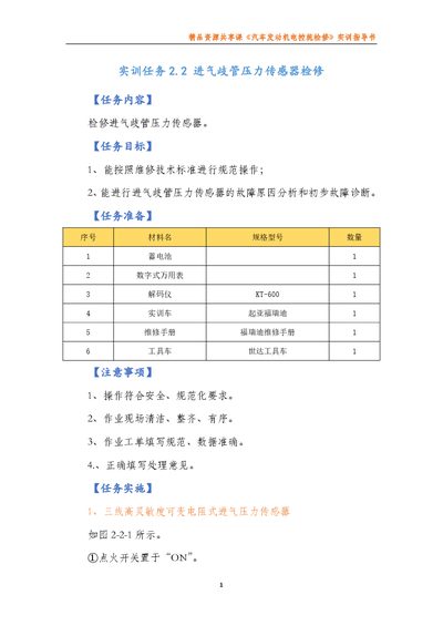
A training guide for repairing and testing intake manifold pressure sensors on automotive engine control systems.
About this manual
This guide provides step‑by‑step instructions for inspecting, testing, and diagnosing three types of intake manifold pressure sensors used in vehicle engine control systems. It includes safety precautions, required tools, and detailed measurement procedures using a multimeter and oscilloscope.
The document also outlines the preparation of the training vehicle (Kia Freed) and references specific sensor wiring diagrams and voltage expectations at various engine speeds and vacuum levels. This manual is written in Chinese.
What's inside
- Training Tasks
- Intake Manifold Pressure Sensor Repair
- Task Content
- Task Objectives
- Task Preparation
- Safety Precautions
- Implementation Steps
- Three‑wire Variable Resistor Sensor
- Semiconductor Pressure Sensor
- Membrane Box Sensor
Specifications
| Vacuum pressure test range | 13.3 kPa (100 mmHg) to 66.7 kPa (500 mmHg) |
|---|
| Membrane box sensor idle voltage | ~0.4 V at idle, increasing with engine speed |
|---|
| Membrane box sensor voltage without vacuum | ~1.5 V |
|---|
Frequently asked questions
What voltage should I expect from the membrane box sensor when the engine is idle?
The voltage should be about 0.4 V at idle and rise gradually as engine speed increases.
How is the semiconductor pressure sensor checked for reference voltage?
Turn the ignition OFF, disconnect the sensor plug, then turn the ignition ON (engine not started) and measure the voltage between Vc and E2 terminals with the multimeter.