
Key facts
- Manuals
- 4
- Models
- 1
- Languages
- ZH
- Last added
- 2026-10-03
Maxsine models by category
Featured Maxsine manuals
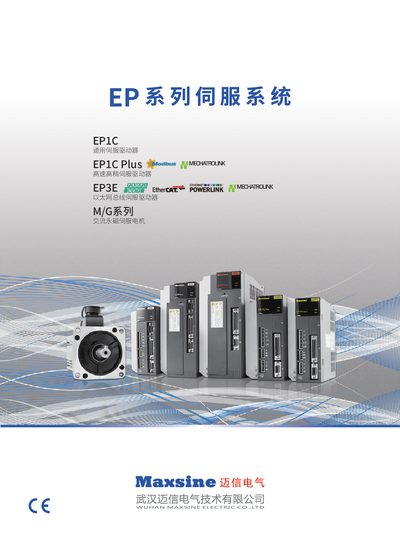
Maxsine EP1C Series Servo Drive Product Data Sheet
The Maxsine EP1C series includes general‑purpose, high‑speed/high‑precision and Ethernet‑bus servo drives (EP1C, EP1C Plus, EP3E) as well as the M/G series AC permanent‑magnet servo motors. They are designed for CNC machines, robotics, printing, packaging and other industrial automation applications.
The document provides detailed technical parameters, wiring diagrams, communication protocol options (Modbus, MECHATROLINK‑II, CAN, PROFINET/EtherCAT), motor compatibility tables and ordering information for the various power ratings and configurations. This manual is written in Chinese.
Covers: Product Overview · Technical Specifications · Communication Interfaces · Wiring and Terminal Assignments · Motor Compatibility · Ordering Information
Maxsine EP100 Series AC Servo Drive User Manual
This manual covers product inspection, installation, wiring, interface connections, parameter settings, protection functions, display and keyboard operation, and running procedures for the Maxsine EP100 series AC servo drives. It includes safety precautions, recommended environmental conditions, and detailed wiring guidelines.
The specification section lists electrical ratings, operating temperature ranges, humidity limits, speed response, and other technical data needed for proper integration and maintenance of the servo drive in industrial applications. This manual is written in Chinese.
Covers: Product Inspection and Installation · Wiring · Interface · Parameters · Protection Functions · Display and Keyboard Operation
Maxsine EP100 Series AC Servo Driver Simple Manual
The document describes how to inspect, install and configure the Maxsine EP100 series AC servo drivers. It covers environmental requirements, motor mounting, wiring specifications, standard connections for position, speed and torque control, and the function of each control signal.
Key sections include product inspection and installation, detailed wiring guidelines, interface terminal definitions, and a full specification table with dimensions, power ratings and performance limits. The manual also lists safety precautions such as grounding, surge protection and waiting periods after power removal. This manual is written in Chinese.
Covers: Product Inspection and Installation · Motor Installation and Environmental Conditions · Wiring Specifications · Standard Connections (Position, Speed, Torque) · Interface and Control Signal Definitions · Specifications
Latest Maxsine manuals
Maxsine EP1C Series Servo Drive Product Data Sheet
Datasheet 36 pages · 7.3 MB · ZHTechnical data sheet for Maxsine EP1C, EP1C Plus, EP3E and M/G series servo drives, including specifications, wiring and communication options.
Maxsine EP100 Series AC Servo Drive User Manual
User Manual 100 pages · 2 MB · ZHThe Maxsine EP100 series AC servo drive user manual provides installation, wiring, operation, safety and specification details.
Maxsine EP1 series alternating servo driver simple Manual
Maxsine EP100 Series AC Servo Driver Simple Manual
User Manual 43 pages · 869 KB · ZHThis manual provides installation, wiring, interface and specification details for Maxsine EP100 series AC servo drivers.
Which document do I need?
Datasheet
Ratings, dimensions and ordering codes, for selection and design work.
User Manual
Day-to-day operation, settings and troubleshooting. Start here if the product is already set up.
Questions answered in Maxsine manuals
What communication protocols does the EP1C Plus support?
The EP1C Plus supports Modbus and MECHATROLINK‑II protocols, and optional CAN or RS‑485 interfaces can be ordered.
What is the protection rating of the EP1C servo drive?
The EP1C servo drive has an IP20 protection rating.
What wire gauge should be used for the main power terminals?
The main power terminals (R, S, T, PE, U, V, W) require a wire gauge of at least 1.5 mm² (AWG14‑16).
How long can the signal and encoder cables be?
Signal cables should be no longer than 3 m, and encoder cables no longer than 20 m.
What does the SON control signal do?
SON ON enables the driver to operate; SON OFF disables the driver, stopping the motor and leaving it in a free‑run state.