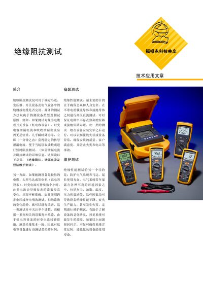
The Fluke application note describes insulation resistance testing principles, methods, safety practices, and procedures for motors, transformers, cables…
About this manual
This document provides an overview of insulation resistance testing, explaining why the test is performed, what equipment can be evaluated, and the overall objectives such as ensuring safety, verifying installation quality, and extending equipment life.
It covers safety guidelines, preparation steps, selection of test voltage, detailed test procedures (installation, verification, preventive maintenance, step‑voltage, dielectric absorption, and polarization index), as well as recommended voltage ranges, temperature corrections, and minimum impedance values for different equipment ratings. This manual is written in Chinese.
What's inside
- Introduction
- Safety Guidelines
- Test Principles
- Test Methods
- Installation Test
- Verification Test
- Preventive Maintenance Test
- Step‑Voltage Test
- Dielectric Absorption Test
- Polarization Index Test
Specifications
| Verification test voltage range | 500 V to 5000 V |
|---|
| Minimum impedance for equipment ≤1000 V | ≥ 1 MΩ |
|---|
| Impedance increase per 1000 V above 1000 V | ≈ 100 Ω per 1000 V |
|---|
Frequently asked questions
What voltage range is recommended for verification testing?
Verification testing typically uses a single voltage between 500 V and 5000 V.
What are the basic steps to perform a verification test?
Press the test key, apply the required voltage, and read the impedance value displayed by the tester.