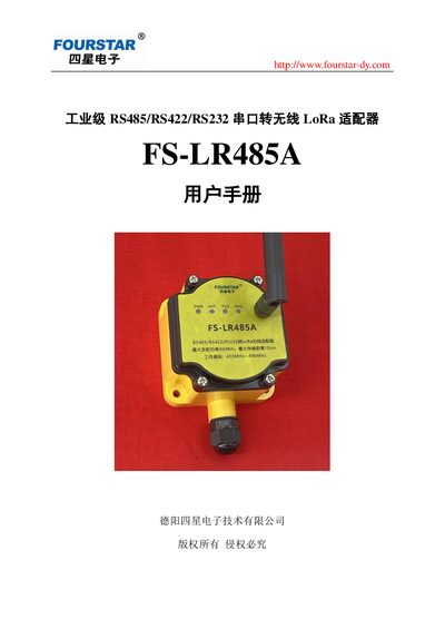
User manual for the Four Star FS-LR485A industrial serial‑to‑LoRa adapter, covering setup, parameters and installation.
About this manual
The FS-LR485A is an industrial‑grade serial‑to‑LoRa wireless adapter that converts RS485, RS422 or RS232 signals to LoRa transmission. It supports up to 65,535 nodes, operates in the 433 MHz band and works in temperatures from –40 °C to +85 °C.
The manual provides detailed hardware specifications, wiring diagrams, parameter configuration via USB, installation guidelines, and troubleshooting FAQs to help users integrate the adapter into automation, IoT or security systems. This manual is written in Chinese.
What's inside
- Overview
- Features and Technical Parameters
- Product Structure and Components
- Antenna and Indicator LEDs
- Wiring Terminals
- Parameter Setting via USB
- Installation Guidelines
- Troubleshooting FAQ
- Ordering Information
Specifications
| Frequency range | 410.125 MHz – 493.125 MHz (84 channels) |
|---|
| Transmit power | 21 dBm – 30 dBm (adjustable) |
|---|
| Receive sensitivity | -148 dBm |
|---|
| Air data rate | 2.4 kbps – 62.5 kbps (adjustable) |
|---|
| Maximum wireless range (open area) | 10 km |
|---|
| Serial baud rate | 1200 bps – 115200 bps |
|---|
| Power supply | 9 V – 40 V DC, 3 W |
|---|
| Operating temperature | -40 °C – +85 °C |
|---|
| Dimensions (L×W×H) | 58 mm × 80 mm × 116 mm |
|---|
| Ingress protection | IP65 |
|---|
| Weight | 200 g |
|---|
Frequently asked questions
Which serial interfaces does the FS-LR485A support?
It supports RS485, RS422 and RS232 interfaces that follow the UART asynchronous protocol, such as MODBUS RTU/ASCII and free‑form serial communication.
How should termination resistors be installed for RS485/RS422 connections?
When using RS485, place a 120 Ω termination resistor at each end of the bus (D+/T+ and D‑/T‑). For RS422, install a 120 Ω resistor on the R+ and R‑ terminals at both ends of the cable.
What causes garbled characters on the serial port and how to fix it?
Garbage characters occur when the baud rate, data bits, parity or stop bits of the adapter do not match those of the connected device; set the parameters to be identical on both sides.
How can the adapter be installed in a metal cabinet without losing signal?
Replace the built‑in antenna with a suction‑cup antenna and route it outside the cabinet to maintain line‑of‑sight for the LoRa signal.