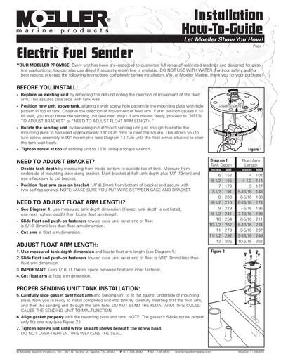
This Moeller Marine guide explains how to install, adjust, and wire the MM044112004R1 electric fuel sender safely.
About this manual
The guide provides step‑by‑step instructions for installing the electric fuel sender, including bracket and float‑arm adjustments, proper tank sealing, and wiring connections. Safety warnings and a leak‑test procedure are also included.
Key steps cover measuring tank depth, cutting and positioning the mounting bracket, trimming the float arm to the correct length, securing the unit with the specified torque, and performing a 3 PSI leak test before final wiring.
What's inside
- Before You Install
- Adjust Bracket
- Adjust Float Arm Length
- Proper Tank Installation
- Wiring Installation
- Leak Test
Specifications
| Top screw torque | 15 in‑lb |
|---|
| Leak test pressure | 3 PSI |
|---|
| Ground wire connection | 1/4" fasson terminal |
|---|
Frequently asked questions
How do I adjust the bracket for the correct tank depth?
Measure the tank depth, mark the bracket at half the depth plus 1/2", cut the bracket, then position the float‑arm case 1/4" from the bottom and secure it with two self‑tap screws.
What torque is required for the top screw?
The top screw should be tightened to 15 in‑lb using a torque wrench.
How can I test for leaks after installation?
Pressurize the tank to 3 PSI and apply soapy water to look for bubbles indicating a leak.
What safety precautions should I follow during installation?
Ensure the tank is empty of fuel and fumes, keep the area free of sparks and flames, and seek professional assistance if unsure about wiring or procedures.