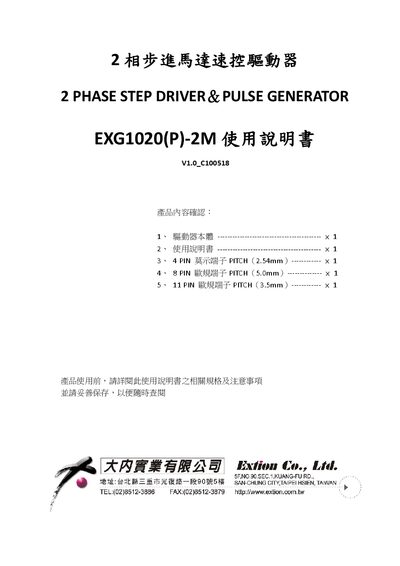
The Tamagawa EXG1020(P)-2M user manual provides specifications, wiring diagrams, signal descriptions, and troubleshooting for the 2‑phase stepper motor driver.
About this manual
This manual describes the features and operation of the Tamagawa EXG1020(P)-2M 2‑phase stepper motor driver, including its compact design, four speed‑range settings, and plug‑in European terminals for easy wiring and maintenance. It also explains how to configure speed, acceleration, and direction using the built‑in switches and external potentiometers.
Detailed specifications such as input voltage, drive current, operating temperature, and weight are listed, along with wiring diagrams, LED indicator functions, signal definitions, switch setting tables, and a troubleshooting guide. The document also contains timing diagrams and physical dimensions to aid installation and service. This manual is written in Chinese.
What's inside
- Product Features
- Specifications
- Signal Description
- LED Indicators
- Wiring Diagram
- Switch Settings
- Troubleshooting
- Operation Timing Diagram
- Physical Dimensions
Specifications
| Input voltage | DC24‑36V, ≥2.5A |
|---|
| Drive current per phase | 0.5A‑2.0A |
|---|
| Operating temperature | 0‑40 °C |
|---|
| Weight | ≈300 g |
|---|
Frequently asked questions
What does the ALM LED indicate?
The ALM (abnormal) LED lights when the driver detects an abnormal condition.
How is external speed set using the potentiometer pins?
Connect an external variable resistor to VR1 (PIN1) or VR2 (PIN2); a voltage of 0‑3 V applied to the resistor controls the speed.