
Key facts
- Manuals
- 1
- Languages
- EN
- Last added
- 2012-02-01
Featured VT-SWKA-1 manuals
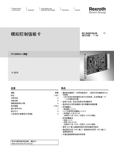
Bosch Rexroth VT‑SWKA‑1 Analog Control Card Service Manual
This manual describes the VT‑SWKA‑1 analog control card, a board used for generating and processing control‑value signals in hydraulic systems. It covers the card’s features, order codes, functional description, wiring diagram with pin assignment, technical specifications, indicator and adjustment elements, unit dimensions, and engineering/maintenance notes.
The document also explains configuration of differential and current inputs, ramp‑time adjustment, polarity switching, and safety precautions for installation and operation. Wiring diagrams, connector details, and measurement points are provided to aid technicians in setup and troubleshooting.
Covers: Features · Order Codes · Functional Description · Wiring Diagram / Pin Assignment · Technical Data · Indicators / Adjustment Elements
Latest VT-SWKA-1 manuals
Bosch Rexroth VT‑SWKA‑1 Analog Control Card Service Manual
Service Manual 8 pages · 606 KB · ENThe service manual for the Bosch Rexroth VT‑SWKA‑1 analog control card provides features, wiring diagrams, technical data, and maintenance instructions.
Which document do I need?
Service Manual
Disassembly, diagnostics and part numbers, for repair.
Questions answered in VT-SWKA-1 manuals
How are the control‑value inputs configured?
Control‑value inputs can be set via potentiometers or external ±10 V signals; differential inputs use ±10 V, and current inputs accept 4‑20 mA (0‑100 %).
From: Bosch Rexroth VT‑SWKA‑1 Analog Control Card Service Manual
What does the green “Ready” LED indicate?
When the power supply is active and no error is present, the green LED on the front panel lights, indicating the “Ready” signal.
From: Bosch Rexroth VT‑SWKA‑1 Analog Control Card Service Manual