
Key facts
- Manuals
- 1
- Languages
- EN
- Last added
- 2023-11-03
Featured I-Gard manuals
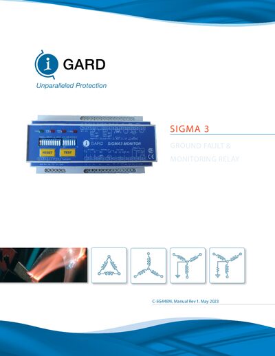
I-Gard C-EG44EM Ground Fault & Monitoring Relay Manual
The SIGMA 3 Ground Fault & Monitoring Relay combines a ground‑fault relay with a neutral‑grounding resistor (NGR) monitor. It measures NGR current, neutral‑to‑ground voltage, and NGR resistance, and provides LED indicators and relay outputs when abnormal conditions are detected. The manual covers system components, dip‑switch settings for trip level and time, pulsing techniques for fault location, and integration with the SIGMA 3‑TDM touchscreen display.
Installation, commissioning, MODBUS communication, and detailed technical specifications are included, along with dimensional drawings and part numbers. The document also explains LED behavior, manual reset procedures, and safety features such as fail‑safe and shunt‑trip modes.
Covers: Introduction · Description · Operation · Trip Relay and Auxiliary Fault Relays · LED Indicators and Diagnostics · Settings
Latest I-Gard manuals
I-Gard C-EG44EM Ground Fault & Monitoring Relay Manual
User Manual 45 pages · 3.3 MB · ENThe I‑Gard C‑EG44EM SIGMA 3 Ground Fault & Monitoring Relay manual provides installation, operation, settings, and troubleshooting guidance.
Which document do I need?
User Manual
Day-to-day operation, settings and troubleshooting. Start here if the product is already set up.
Questions answered in I-Gard manuals
How is the ground fault trip level set?
The ground fault trip level is DIP‑switch selectable as a percentage of the NGR let‑through current setting (5 %‑50 %).
From: I-Gard C-EG44EM Ground Fault & Monitoring Relay Manual
Which LED indicates a detected ground fault?
The red GND FAULT LED turns on when the SIGMA 3 detects and qualifies a ground fault.
From: I-Gard C-EG44EM Ground Fault & Monitoring Relay Manual